Issues with Concentric Reducers in the Foam Suction Line of Foam Poroportioners
For the foam firefighting system at a Dangerous Goods storage facility, a FireDos FD6000/3-S unit equipped with new EV valve cones was installed. The foam concentrate used was a fluorine-free, non-Newtonian formulation, and based on its viscosity data, the FireDos unit was expected to operate without flow limitations within its FM-approved range.
A thorough review of the foam concentrate suction line including pipe length, fittings, and valves confirmed compliance with the design standards and compatibility with the foam concentrate.
Unexpected Performance Drop
During site testing, the system achieved the target proportioning rate for flow rates up to 4500 LPM. However, at higher flow rates, the proportioning rate dropped below 3%, falling short of the required performance despite the suction line design and foam concentrate data being previously validated.
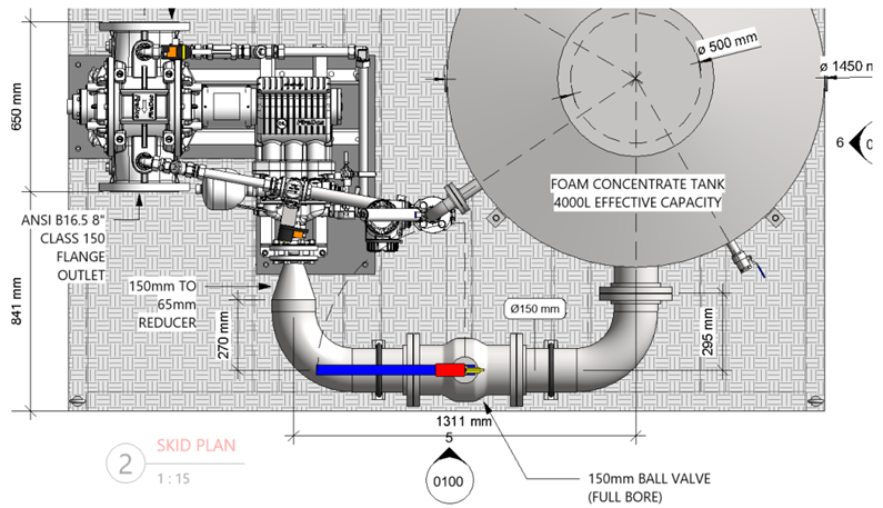
To identify the cause, the drawings were further reviewed, and it was discovered from the general arrangement drawings that a concentric reducer had been installed at the tie-in point to the FireDos foam concentrate inlet. Specifically, a 6” suction line was reduced to the 2½” inlet using a concentric reducer.
Root Cause Analysis
Concentric reducers maintain a centerline alignment between larger and smaller pipe diameters. When installed horizontally, they allow air pockets to form at the top, especially if the pipe isn’t fully flooded.
These trapped air bubbles can:
- Be drawn into the pump
- Result in improper proportioning
- Cause cavitation, leading to
-
- Vibration & noise,
- reduced pump efficiency
- potential damage to pump internals
In contrast, eccentric reducers, when installed with the flat side up, allow air to flow freely along the top of the pipe, preventing air entrapment and ensuring stable suction conditions.
Resolution
Since the concentric reducer was already installed and couldn’t be replaced, FireDos recommended installing a vent at the top of the reducer to release trapped air.
Following the installation of the vent, a performance test was conducted at the unit’s maximum flow rate of 6000 LPM. Once the air was vented, the system achieved the target proportioning rate, confirming that air entrapment in the concentric reducer was the root cause of the earlier performance drop.
Design Recommendations for Foam Suction Line
To avoid similar issues and ensure optimal performance of foam proportioning systems, the following best practices should be applied when designing foam concentrate suction lines:
- Keep suction pipes short and straight
- Avoid elevation changes ("ups and downs")
- Use eccentric reducers with the flat side up in horizontal suction lines
- Avoid dead ends
- When using multiple foam tanks, connect them in series
- Provide dedicated suction lines from the foam agent tank to each foam pump
- Perform accurate calculations to size suction pipes correctly
- Ensure the foam tank outlet matches the suction pipe diameter
- Use uniform pipe sizes for all fittings in the suction line
- Do not install spring-loaded check valves or filters in suction piping
- Ensure the entire suction line is vacuum-tight to prevent air ingress
This might also be of interest for you:

IBCS containers as foam agent tank
Learn what needs to be considered connecting an IBC as foam agent tank.
View more
Stationary foam proportioners
Reducing costs, enhancing performance - explore the advantages
View more
FireDos Service Team: Always there for you
From planning to maintenance: We are happy to assist you.
View more